The equation seems appropriate. First separate the object into rectangles and then calculate the weight.

Design Analysis And Weight Optimization Of Crane Hook A Review Semantic Scholar
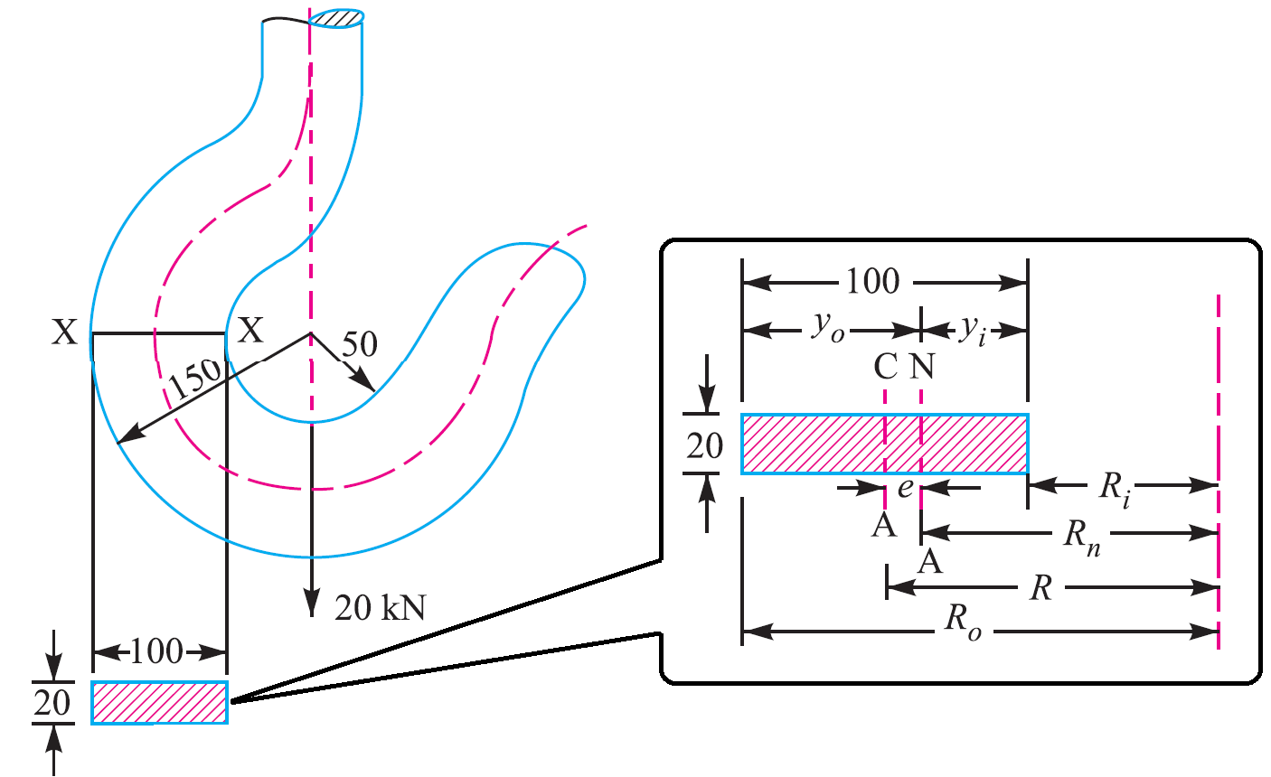
From the above equations Calculated values The radius of curvature of the neutral axis R n 9107 mm The radius of curvature of the Centroidal axis R 100mm The.
. Ricker Per AISC 13th Edition ASD Manual ASME BTH-1-2008 and Tensile Strength of Lifting Lug ASME Eqn. Q 1 kNm² for oiled steel mould. Another important consideration is the centre of.
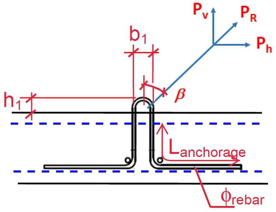
Angle of pull When slings are used the angle of pull βdepends on the length of the suspending cable. Using the design calculation from the modeling the analysis of hook is done in FEA software This result lead us to the determination of stress in existing model. They applied curved beam theory Finite Element Method and photo elasticity.
Min 1 ξ. Calculations to be made will include the capacity both of the overall beam and of the loading of the individual lifting points. The design of the crane hook is rather simple and its use is restricted to the lifting of heavy loads performed in the thermal ie.
They applied curved beam theory Finite. Q 2 kNm² for varnished timber mould. The design of below-the-hook lifting devices are standardized in the United States by ASME B3020 and further detailed in Below-the-Hook Lifting BTH-1-2008 Design of Below.
Al 2009 this paper presents the different methods of stress calculation for lifting hooks based on different assumptions. A lifting hook is a device for grabbing and lifting loads by means of a device such as a hoist or crane. By varying the lengths of chokers a fixed-tilt lifting beam can be made as depicted in Fig.
However As such standards do not clearly address the local stress calculation steps Finite Element Analysis is performed using various. 115 min1ξmax1ξV L. Cr P5 Bearing.
ASME BTH-1 specifies design calculations for different types of loading of a lifting device including tension compression flexure shear and combined loading of beams. LIFTING SYSTEMS DESIGN CRITERIA LIFTING SYSTEMS DESIGN CRITERIA We have four main systems available for the lifting of precast concrete units. 3C the sling lengths can be calculated using the.
Q 3 kNm² for rough timber mould. Max 1 xi cdot V_ L. A lifting hook is usually equipped with a safety latch to prevent the.
ASME BTH-1 Standard Design of Below the Hook. 115 with ξ 03 for fixed crane or on rails and ξ. Lifting hook material Prestressing strands When prestressing strands are used Ultimate tensile stress Fpu 1860 Nmm2 Diameter of strand Dia 953 mm Area of prestressing strand As.
ASME BTH-1 Design of Below-The-Hook Lifting Devices governs the design of lifting lugs for industries. Full rated lifting capacity of the sling may be utilized but must not be. Formwork adhesion Ha is calculated through the following equation.
Basic Lift Engineering STRAIGHT OR VERTICALattachment is simply using a sling to connect a lifting hook to a load. A lifting beam is the ideal method of lifting if site conditions permit. Ha q x A kN A.
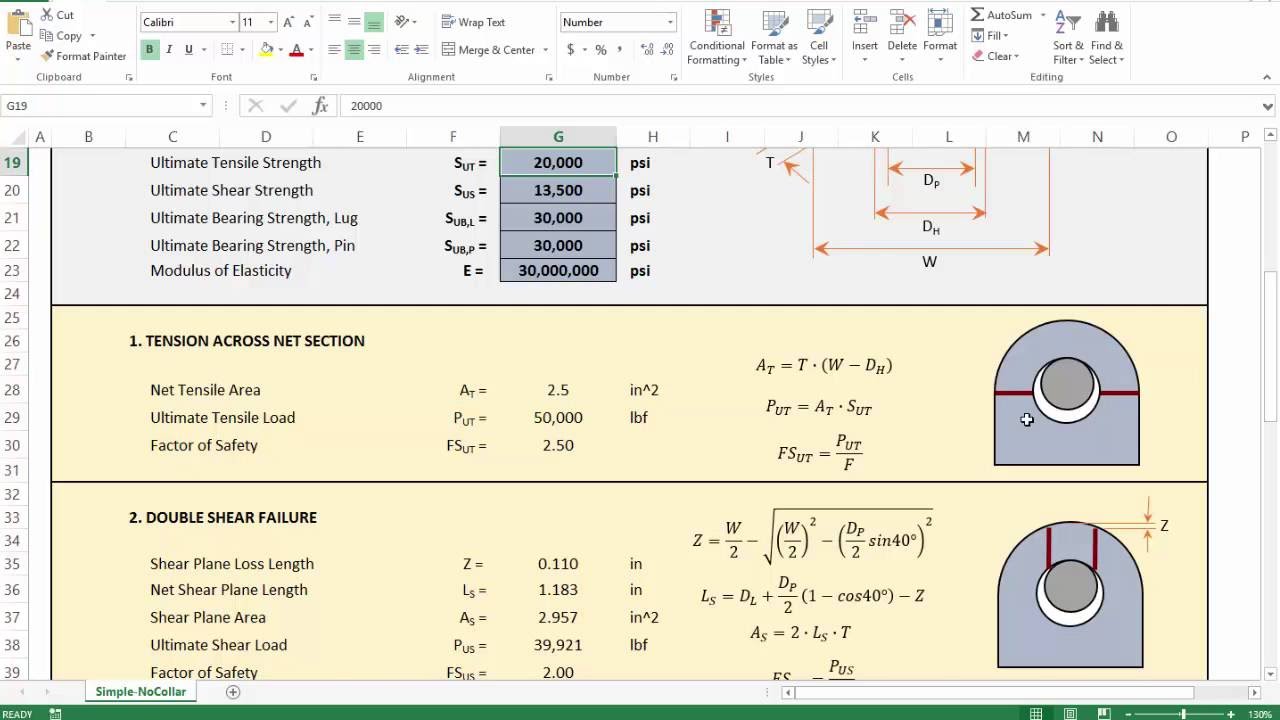
For producing a safe reliable design This is the most widely used lifting lug design standard. My concern is the coding in the excell spreadsheet in which leaving out the parenthesis makes a significant difference. Hot regions where the crane hook gets.
Tension on Sling T 1 2 V1 2. Dynamic factor. Area of contact between the mould and the concrete unit when starting to lift.
To attach the load locate the center of gravity position the crane hook directly above the center of gravity and then rig the load so that it will lift level and true. The reasons for selection may be. By predicting the stress.
Expressed in terms of variables noted in Fig. Lifting Devices arises after the creation by ASME of a design task group in 1997 to develop a design standard that complements the. Max 1 ξ V L.
This is calculated by dividing the bending moment on the lifting beam by its section modulus. Heres how you would calculate the load weight of an irregular shaped object made out of concrete. Design and Construction of Lifting Beams by David T.
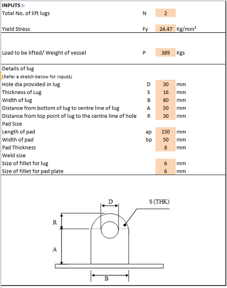
1 5 min 1 xi. DesignEvalution of Overhead Lifting Lugs Page 2 Pw2 16875kip Pw2 09Fytdpin 18 dpin d 050 in This failure mode involves bearing failure at the pinlifting lug interface.
Crane Hook Design Problem Sample Extrudesign

Technical Drawing Of Hook Number 12 Download Scientific Diagram

Lifting Lug Design With Example What Is Piping
Lifting Lug Design Spreadsheet Calculator
4 Lifting Lug Analysis Simplified Youtube
2
Rys Precast Lifting Design
2
0 comments
Post a Comment